|
|
|
Digital Elevation Model's and some Three-dimensional Display Capabilities of ER Mapper Software
by : Idung Risdiyanto
MIT Student / Biotrop
1999
![]()
![]()
![]()
Brief Explanation
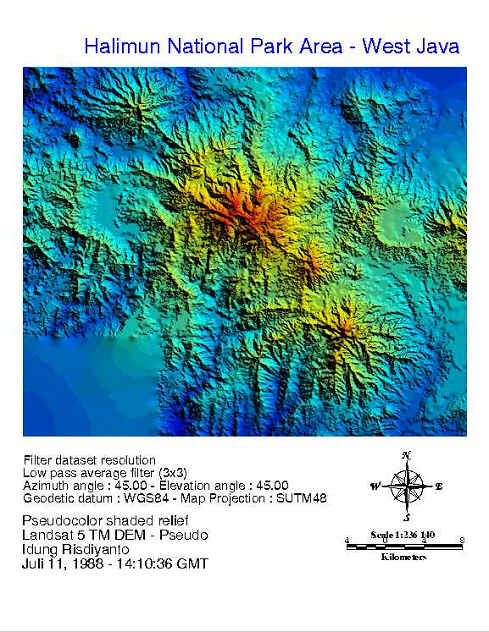
Digital Elevation Models are representation as a regular grid of numbers. The
spacing between grid elements represents the interval between samples. The
numerical value in each grid element represents the elevation at that point.
This is often a floating-point number, to ensure that small variations in
elevation can be record accurately. If
we use the software image processing especially the ER Mapper software, we can
be displaying or view the DEMs into the 2D and 3D prespective mode.
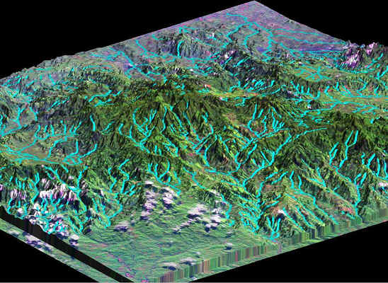
Texture draw mode: The 3D image will be presented the texture of surface and if we see and compare with the composite image before add the height layer we will found that the texture draw mode do not change the color of image. For example, the green color (vegetation) the highland (Halimun peak) and the its forest do not change or the sun angle do not influence the image like as if we use do-sunshading.
Wireframe draw mode: The image can be quickly displaying. The wire frame can consist of horizontal (H), vertical (V) or both horizontal and vertical (HV) lines. But, sometimes the display not clearly because the viewing generate is quickly and building the line by line in each of pixel to be contained the floating point.
Smooth shaded draw mode : Similar as the 2D shaded relief, but in this the viewer is the 3D perspective. The image has the some part is dark and some part is light. Therefore we use the composite (RGB 741) image as the base, so, the color image will be changes become darker or lighter.
Based
on the choosing of the draw mode and memory of computer capability, we can make
the detail viewer and see the vector layer more clearly, we can increase the terrain detail that we want.
We also make the bounding box using bounding box check in the 3D view
list. If we use it, the 3D image
will be put into the transparent box and may be will help us to know the border
or limit axis of the area on the image.
The
others options to change the viewer can we select from the others sheet in the
algorithm window. For example, from
the 3D properties we can get the information about the z scale and z offset and
the others.
Last one, the 3D viewing can use for understanding how the real surface on the earth if we see from the image. Using 3D viewing we also can change the direction of the see or our eyes so that we can know what happened or the reality if we see from other direction. For application, 3D viewing is very important for the train of the pilot, especially for the sky acrobatic use the jet plane or fighter plane. Using the 3D simulator of the earth surface, the pilot will be train and learn how to controlled the plane if it is scrolling or others maneuver or acrobatic moves.
These are few example of the result this assignment :
3D Perspective
![]()
![]()
![]()
![]()